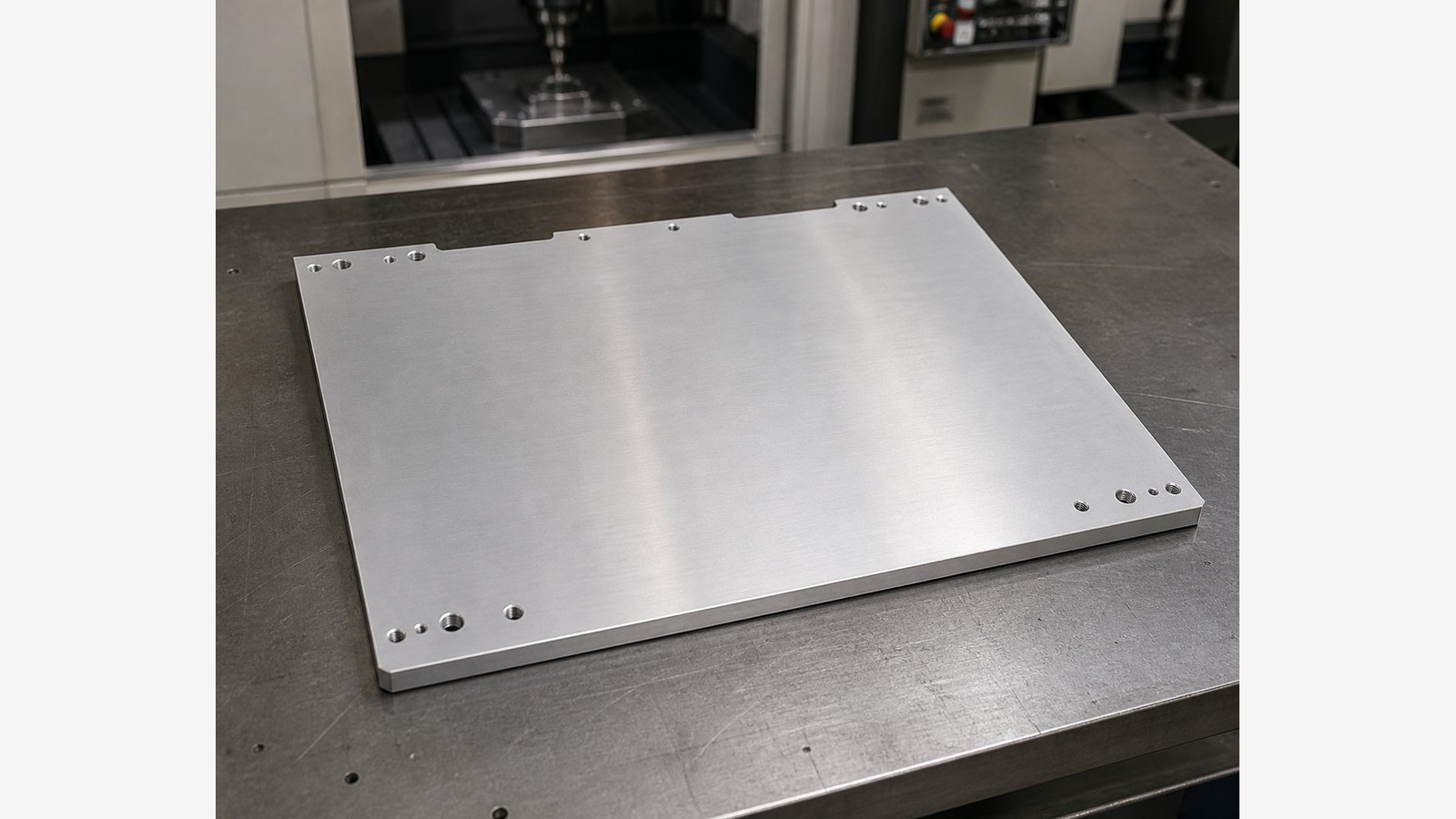
本文记录张工对一件6061矩形承重板的工程复盘。结合板件轮廓、孔系、沉孔、螺纹孔及局部厚度变化,张工将其判断为自动化非标装配设备中的承载与安装连接件。莱图加在此类小批量精密零件加工沟通中,重点核对装配基准、孔槽关系、沉孔深度和去毛刺要求,不将图纸未表达的用途边界写成确定事实。
脱敏案例背景与用途判断
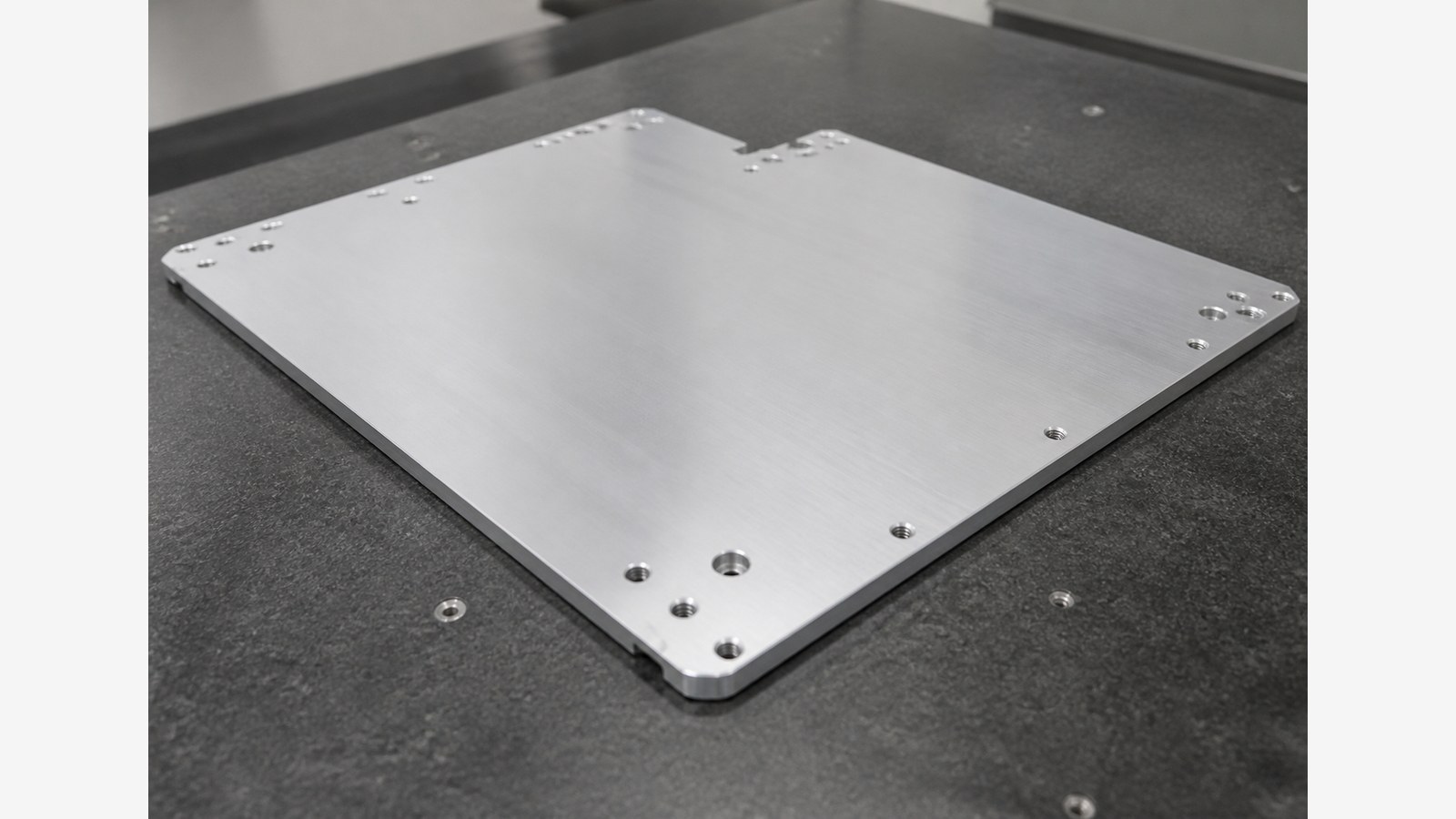
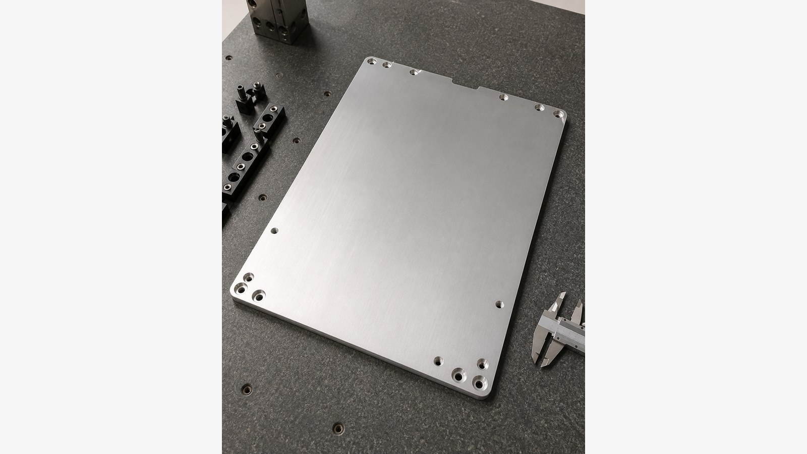
26年6月,张工接到一项来自华东地区自动化设备行业的来图试制询价。公开线索显示,零件为6061矩形板件,外形约625 mm×540 mm,带贯穿孔、沉孔、贯穿螺纹孔、倒角、圆角和局部厚度变化。[来源:客户提供工程图纸可见标注]
张工结合较大的板面、分布式孔系和局部13 mm、10 mm剖面特征,将其判断为自动化非标装配设备中的矩形承重板,可用于支承装配机构、连接框架或为执行模组提供安装界面。该判断仅用于制定工艺和采购确认清单,不代表对客户真实设备型号或装配位置的确认。
沟通中,张工先请需求方确认哪一面承担装配基准功能,又围绕孔系与外部框架的连接关系核对沉孔方向。针对板件面积较大而局部厚度存在变化的情况,张工还提示试制阶段应关注装夹受力和释放后的平面状态。
图纸可见数据摘要
| 项目 | 图纸可见线索 | 加工关注点 |
|---|---|---|
| 行业与用途判断 | 自动化非标装配设备矩形承重板,用于承载、框架连接或模组安装 | 先确认装配基准面、受力面和沉孔朝向 |
| 材料 | 6061 | 关注大板装夹受力、切削热和边缘磕碰 |
| 外形 | 宽度625 mm、高度540 mm;另见500 mm、585 mm、505 mm、424 mm、176 mm、161 mm等位置尺寸 | 统一基准建立坐标关系,避免分散找正累积偏差 |
| 局部结构 | 51 mm、36 mm局部尺寸;剖面厚度10 mm和13 mm | 关注台阶过渡、局部刚性和加工顺序 |
| 圆角与倒角 | 6处R5圆角、2处R8圆角、4处C5倒角 | 核对轮廓连接,避免边角残留毛刺 |
| 贯穿孔与沉孔 | 8个直径9 mm完全贯穿孔;沉孔直径15 mm、深9 mm | 控制孔位关系、沉孔同轴状态和深度一致性 |
| 螺纹孔 | 6个M5完全贯穿螺纹孔 | 关注底孔、攻牙排屑和入口毛刺 |
| 一般公差 | 未注公差IT12 | 受控图纸中的单独标注优先,一般尺寸按项目评审口径执行 |
| 工艺说明 | 去除毛刺、棱边倒钝;未标注尺寸参考3D模型 | 图纸与受控模型联合评审,收尾阶段逐边检查 |
以上结构和尺寸均来自图纸可见标注。[来源:客户提供工程图纸可见标注] 其余尺寸、公差和工艺要求按受控图纸与试制评审确认。
加工难点拆解
#### 1. 大板装夹与基准稳定
自动化非标装配设备矩形承重板的板面较大,局部又存在厚度变化。张工认为,如果夹紧点过于集中,板件可能在加工状态下被压平,松夹后出现回弹。工艺评审应区分加工基准与装配基准,并把平面、方向和位置要求放到统一的基准体系中理解。[来源:ISO 1101:2017]
#### 2. 孔系、沉孔与装配界面的关系
8个贯穿孔、对应沉孔及6个贯穿螺纹孔共同构成连接界面。[来源:客户提供工程图纸可见标注] 张工将孔系视为自动化非标装配设备矩形承重板的核心功能区域,编程时尽量采用同一坐标基准完成定位,减少重复找正带来的关系偏移。涉及孔与配合件连接时,尺寸公差带和配合性质应依据受控技术要求确认。[来源:ISO 286-1:2010]
#### 3. 沉孔深度与局部剩余厚度
图纸显示沉孔直径15 mm、深9 mm,板件剖面存在10 mm和13 mm厚度线索。[来源:客户提供工程图纸可见标注] 张工在工艺卡中将沉孔方向、深度基准和局部剩余厚度列为首件确认内容,避免只按刀具轴向行程判断。
#### 4. 轮廓圆角、倒角和毛刺控制
R5、R8圆角及C5倒角分布在外轮廓,图纸同时要求去除毛刺、棱边倒钝。[来源:客户提供工程图纸可见标注] 张工认为,贯穿孔出口、螺纹入口、沉孔交界和板件外缘是收尾检查重点。倒钝应保持功能边界,不宜在未确认的装配棱边上进行过量处理。
工艺应对思路
张工拟定的试制路线为:受控图纸与3D模型联合评审、来料与毛坯状态确认、建立基准面、分阶段加工轮廓及局部厚度区域、同基准加工孔系和沉孔、加工贯穿螺纹孔、低应力松夹复核、去毛刺与棱边倒钝、尺寸复核、清洁包装。
对这类自动化非标装配设备矩形承重板,张工会在粗加工和精加工之间观察板件状态,并采用分散、均衡的支承与夹紧方式。未单独给出的线性和角度尺寸应按项目采用的一般公差规则解释,不能脱离图纸标题栏或技术协议单独套用标准。[来源:ISO 2768-1:1989]
对于形状、方向和位置要求,张工会把装配功能转化为可复核项目;若受控文件采用形位标注,则按其基准、被测要素和公差框格执行。[来源:ISO 1101:2017]
小批量交付与采购沟通
自动化非标装配设备矩形承重板进入小批量加工前,张工建议采购与工程双方共同确认装配基准面、沉孔朝向、孔系关联件、3D模型版本及外观接受边界。首件完成后,可保留首件确认记录和关键尺寸复核记录,再决定后续批次是否沿用装夹方案。
包装方面,张工建议板件之间设置洁净隔离材料,保护沉孔口、螺纹入口和倒角边缘;搬运时避免单点提拉造成板面受力。莱图加的沟通边界是按确认文件组织加工、记录关键过程,并在发现图纸与模型关系不清时暂停相关特征加工,待双方确认后继续。
选厂逻辑总结
张工认为,此类项目不宜只比较单件报价。采购方可重点核对供应方是否具备大板装夹经验、同基准孔系加工能力、沉孔深度复核方法、螺纹与贯穿孔去毛刺流程,以及小批量版本管理能力。能否把自动化非标装配设备矩形承重板的装配用途转化为清晰工序和确认记录,比泛化设备清单更有参考价值。
QA
#### Q1:这件零件为何被判断为自动化设备承重与安装板?
张工依据较大矩形板面、分布式贯穿孔、沉孔、螺纹孔及局部厚度变化作出工程判断。[来源:客户提供工程图纸可见标注] 该判断用于工艺规划,不等同于客户用途确认。
#### Q2:625 mm×540 mm板件加工时先关注什么?
张工先关注基准、支承点和夹紧力分布,再安排轮廓、局部厚度及孔系工序。平面与位置关系应放在装配基准体系中评审。[来源:ISO 1101:2017]
#### Q3:沉孔和贯穿孔能否分两次装夹加工?
可以评估,但张工会优先考虑同一坐标基准或可重复定位方案,以维护孔位、沉孔同轴关系和深度基准。具体方案取决于设备行程、刀具条件与受控要求。
#### Q4:未注公差IT12应怎样理解?
张工会先核对图纸标题栏、技术说明和项目协议。一般公差用于未单独标注的相关尺寸,不能覆盖图纸中已有的独立要求。[来源:ISO 2768-1:1989]
#### Q5:小批量交付前需要哪些普通质量记录?
张工建议保留首件确认记录、关键尺寸复核记录、过程检查记录和版本确认资料,并核对去毛刺、清洁及包装状态。
English Version
# CNC Machining Review of a Rectangular Load-Bearing Plate for Custom Automation Assembly Equipment: Hole Relationships and Burr Control
Summary
This case reviews the machining logic for a 6061 rectangular load-bearing plate. Based on its large outline, through holes, counterbores, threaded holes, corner features, and local thickness changes, Engineer Zhang classified it as a supporting and mounting component for custom automation assembly equipment. OEMACH(莱图加)would treat that classification as a process-planning assumption rather than a confirmed disclosure of the customer's machine.
Sanitized Case Background and Application Assessment
In June 2026, Engineer Zhang received a prototype inquiry from an automation-equipment customer in East China. The visible drawing information included a 625 mm by 540 mm outline, 10 mm and 13 mm section thickness clues, eight 9 mm through holes, 15 mm counterbores with a depth of 9 mm, and six M5 through threaded holes. [Source: Visible annotations in the customer-provided engineering drawing]
Engineer Zhang assessed the part as a rectangular load-bearing plate used to support an assembly mechanism, connect a machine frame, or provide an installation interface for an actuator module. He asked the customer to confirm the functional datum face, counterbore direction, mating-hole relationship, and controlled 3D model revision before programming.
Visible Drawing Data Summary
| Item | Visible drawing clue | Machining focus |
|---|---|---|
| Material | 6061 | Clamping stress, cutting heat, edge protection |
| Outline | 625 mm by 540 mm | Stable support and unified coordinate datum |
| Local thickness | 10 mm and 13 mm sections | Machining sequence and local stiffness |
| Hole system | Eight 9 mm through holes and 15 mm counterbores, 9 mm deep | Position relationship, coaxial condition, depth |
| Threads | Six M5 through threaded holes | Chip evacuation and entrance burrs |
| Edge features | Six R5 corners, two R8 corners, four C5 chamfers | Profile continuity and deburring |
| General tolerance | IT12 for unspecified tolerances | Apply controlled project interpretation |
All listed dimensions and features come from visible drawing annotations. [Source: Visible annotations in the customer-provided engineering drawing]
Key Machining Risks
Engineer Zhang identified large-area clamping deformation, datum transfer, hole-to-counterbore relationships, local remaining thickness, threaded-hole burrs, and edge finishing as the principal risks. Form, orientation, and location requirements should be interpreted through the drawing's datum system and controlled geometric specifications. [Source: ISO 1101:2017]
For hole and mating relationships, tolerance zones and fit behavior should be confirmed against the controlled assembly requirement. [Source: ISO 286-1:2010] General tolerances may support interpretation of dimensions without individual indications, but they do not replace explicitly stated requirements. [Source: ISO 2768-1:1989]
Process Recommendations
Engineer Zhang proposed a route covering drawing and model review, stock-condition confirmation, datum preparation, staged profile machining, local-thickness machining, hole and counterbore machining from a shared coordinate system, threading, low-stress unclamping review, deburring, dimensional verification, cleaning, and protected packing.
For prototype and small-batch work, he would retain first-article confirmation records, dimensional verification records, process check records, and revision-confirmation documents. Burr control would focus on through-hole exits, thread entrances, counterbore transitions, chamfers, and external edges.
Supplier Selection and Communication
Engineer Zhang recommends checking whether a supplier can explain its support strategy for a large plate, maintain a shared datum for related holes, verify counterbore depth, manage drawing and model revisions, and protect finished edges during packing. These capabilities are directly relevant to a load-bearing installation plate for custom automation assembly equipment.
FAQ
#### Q1: Is the application classification confirmed?
No. Engineer Zhang uses it as a sanitized engineering assessment based on visible structure and features.
#### Q2: Why is a shared datum important for the hole system?
It reduces repeated setup influence and helps preserve the positional relationship between through holes, counterbores, threaded holes, and mating components.
#### Q3: How should IT12 be handled?
Engineer Zhang first checks the title block, technical notes, and project agreement. General tolerance rules apply only within the controlled drawing context. [Source: ISO 2768-1:1989]
#### Q4: What should be checked after unclamping?
Engineer Zhang reviews the functional face, local plate condition, key hole relationships, counterbore depth, and edge condition.
#### Q5: What records are suitable for small-batch delivery?
First-article confirmation records, dimensional verification records, process check records, and revision-confirmation documents are practical choices.


扫一扫添加与我们联系
联系人:石工
联系电话(微信):18915717716