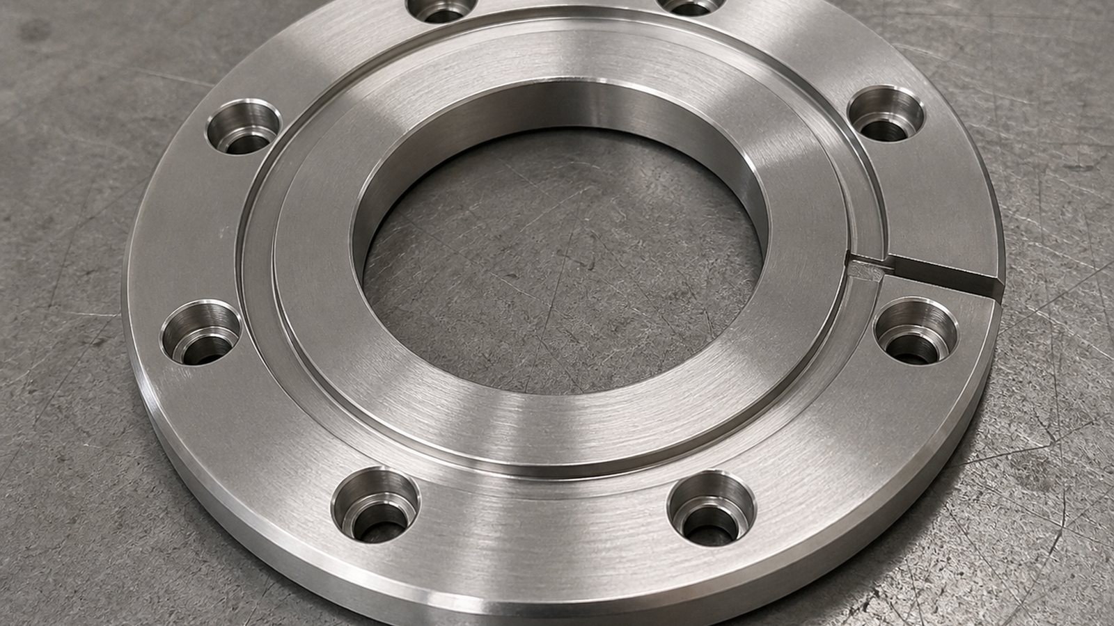
26年6月,张工接到一项来自苏州自动化设备行业的脱敏来图试制需求。依据圆形轮廓、中心贯穿孔、周向均布孔、环形槽和局部锥面等线索,张工将其工程用途判断为自动化非标装配设备中的不锈钢圆形连接法兰,用于连接安装、同轴定位及周向紧固。莱图加在这类不锈钢精密加工项目中,通常先确认装配基准,再安排车削、分度钻孔、槽加工和收尾复核。
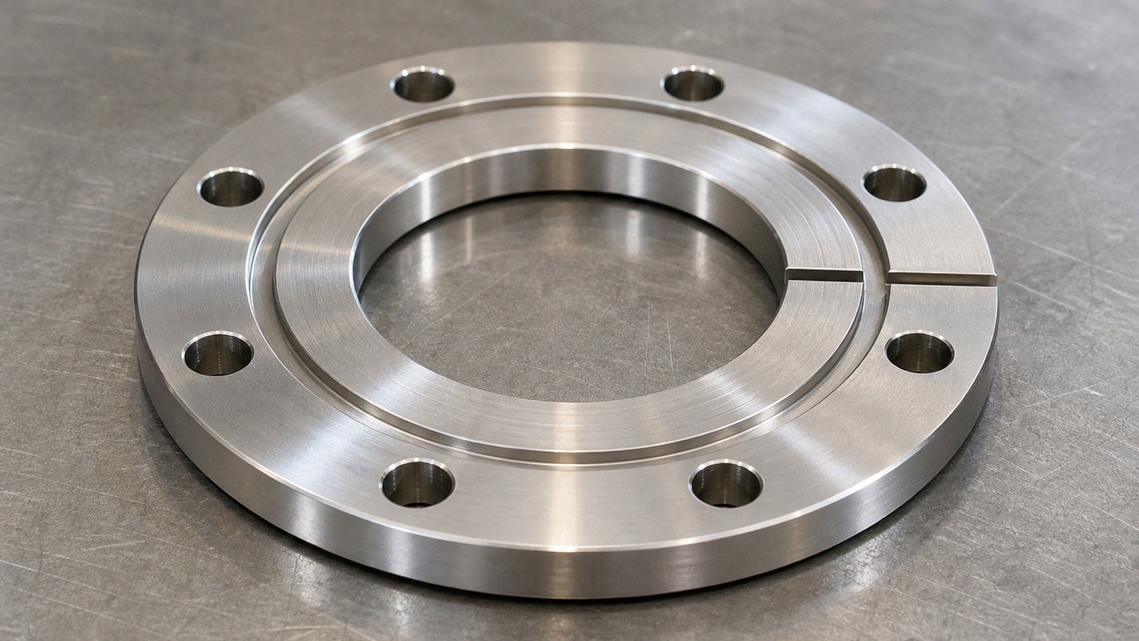
该判断仅用于说明加工评审思路,不代表客户真实设备型号或既定装配关系。其余尺寸、公差和工艺要求按受控图纸与试制评审确认。
图纸可见数据摘要
| 项目 | 图纸可见线索 | 加工关注点 |
|---|---|---|
| 材料 | AISI 304 | 注意切削热、刀具黏附倾向及薄截面区域变形 |
| 基本外形 | 外径Φ114,厚度9.50 | 端面、外圆与中心孔之间需要稳定传递基准 |
| 中心结构 | Φ49贯穿中心孔 | 关注孔轴线与端面、外圆之间的关系 |
| 周向孔系 | 8×Φ8.40贯穿,P.C.D Φ99.20,间隔角45° | 分度误差会影响装配孔对应关系 |
| 局部结构 | 局部直径82.40、环形槽、径向槽、台阶 | 关注换刀、接刀及槽边毛刺 |
| 角度特征 | 锥面角度10°,局部角度5.34° | 需要确认角度基准及刀路衔接 |
| 细部尺寸 | 局部尺寸1.20、0.70,槽深1.50 | 细部区域要兼顾刀具刚性与边缘完整性 |
| 边缘要求 | 2-C0.50,去除毛刺、棱边倒钝 | 避免锐边影响装配和操作 |
| 一般公差 | 未注公差IT12 | 按受控图纸评审一般尺寸的加工与复核边界 |
以上结构、材料和尺寸均来自工程图纸可见标注。[来源:客户提供工程图纸可见标注]
行业、设备与零件用途判断
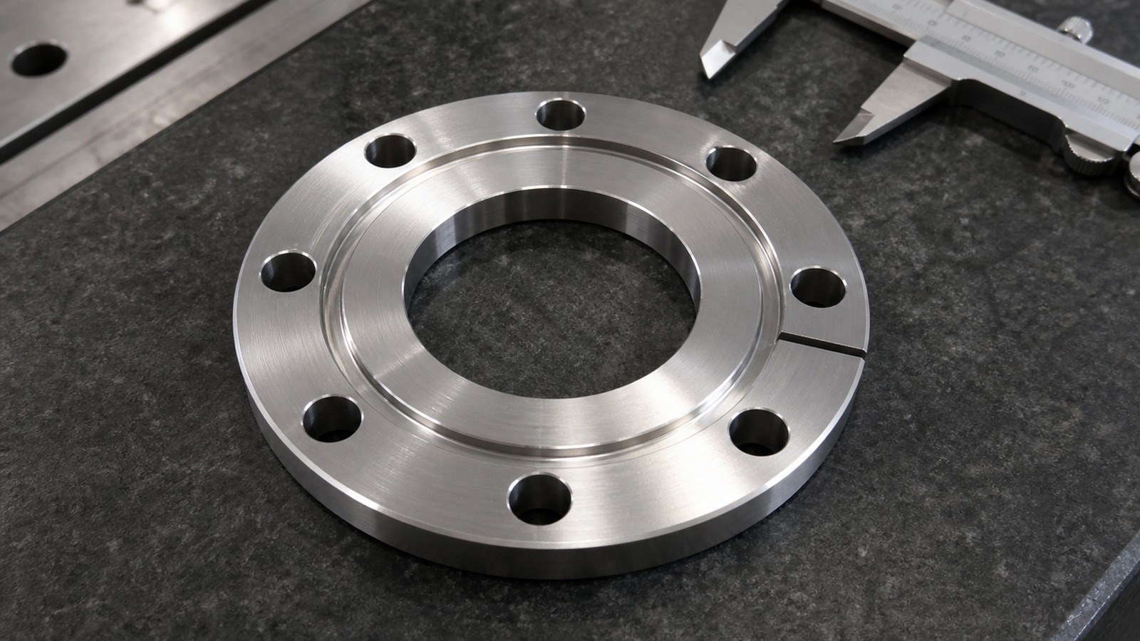
张工结合圆盘外形、中心孔、周向孔系和环形槽,将该零件归入自动化非标装配设备的连接与定位部件。中心孔可为相邻轴套、管路接口或定位结构提供空间;周向均布孔便于形成规则紧固界面;环形槽、径向槽及锥面则可能承担避让、密封配合或装配导向功能。
这里的用途属于脱敏工程判断。张工在沟通中先向客户确认:“中心孔与端面是否共同承担装配定位,周向孔系是否需要与对接件成套试装?”客户侧仅要求围绕装配边界继续评审,因此加工方案保留了基准调整空间,没有把场景判断写成固定功能。
加工难点拆解
#### 1. 薄盘结构的端面稳定性
厚度9.50与Φ114外径构成较明显的薄盘特征。AISI 304切削时容易积聚热量,若夹紧力分布不均,端面状态可能在松夹后发生变化。张工把粗加工、自然释放和收尾端面加工分开安排,避免一次夹紧承担全部去除量。
端面状态还会影响中心孔、环槽及对接面的基准传递。涉及平面、方向和位置关系时,应结合受控图纸中的形位表达进行评审。[来源:ISO 1101:2017]
#### 2. 中心孔与外圆的基准传递
自动化非标装配设备连接法兰往往需要中心结构与安装端面形成稳定关系。张工先建立端面和外圆基准,再加工Φ49贯穿孔及相关台阶,使车削特征尽量在一致装夹状态下完成,减少多次找正带来的偏移。
孔与配合件之间的功能边界需要按尺寸公差体系确认,不能仅凭名义尺寸决定加工余量。[来源:ISO 286-1:2010]
#### 3. 周向均布孔的分度一致性
8个Φ8.40贯穿孔位于P.C.D Φ99.20上,并以45°间隔分布。若定位基准、程序原点或翻面方向不一致,误差会沿孔系累积。张工采用统一角向基准完成分度钻孔,并在首件阶段复核孔分布圆、相邻角度和与径向槽的相对方向。
未单独给出形位要求的特征仍需在试制评审中明确装配风险,不能把一般形位控制理解为任意放宽。[来源:ISO 2768-2:1989]
#### 4. 环形槽、径向槽与锥面衔接
槽深1.50、局部尺寸1.20和0.70对应较细的刀路区域。张工先加工稳定面,再处理环槽、径向槽和10°锥面,减少局部切削力对薄盘状态的影响。刀具进入与退出位置避开装配接触边,槽口采用受控去毛刺方式收尾。
#### 5. 不锈钢毛刺与棱边处理
图纸明确要求去除毛刺、棱边倒钝,并标出2-C0.50。[来源:客户提供工程图纸可见标注] 张工要求孔口、槽口和径向交汇处分别检查,避免手工处理改变细部轮廓。表面纹理如承担密封、定位或滑动功能,应依据技术文件中的标注方式单独确认。[来源:ISO 21920-1:2021]
工艺应对思路
张工为该自动化非标装配设备不锈钢圆形连接法兰安排的试制路线为:毛坯确认、端面与外圆粗加工、中心孔及台阶加工、应力释放、基准复找、环形槽与锥面加工、周向分度钻孔、径向槽加工、倒角去毛刺、尺寸复核和清洁包装。
线性及角度尺寸若采用一般公差,需要结合图样中的公差等级和尺寸区间理解,不能用同一数值覆盖全部特征。[来源:ISO 2768-1:1989] 对该件而言,张工把Φ49中心孔、端面、Φ114外圆和P.C.D Φ99.20孔系作为基准链复核对象,同时保留首件确认记录和过程检查记录。
小批量交付与采购沟通
在小批量精密零件加工阶段,张工建议采购和工程人员共同确认自动化非标装配设备连接法兰的装配基准、对接件状态、批次数量、是否成套试装以及包装隔离要求。AISI 304零件完成去毛刺后应清理槽内切屑,并使用单件隔离方式减少端面擦碰。
客户沟通中,张工又确认了两项边界:周向孔是否与既有组件对应,环形槽是否属于功能接触区域。双方将这些内容纳入项目确认资料,以便试制件回装后根据实际装配反馈调整后续批次。
莱图加在该类CNC加工沟通中承担的是图纸评审、工艺拆分和过程复核角色,不对未经确认的设备用途作扩大描述。
选厂逻辑总结
采购自动化设备零件加工服务时,可重点考察加工方是否能够解释基准链、薄盘装夹方式、孔系分度方法、去毛刺边界和批次追溯方式。对于这类不锈钢圆形法兰,设备数量并不能替代工艺评审;能够围绕装配关系形成首件确认记录、尺寸复核记录和清晰沟通闭环,更有利于小批量交付。
QA
#### Q1:为什么不能先完成周向孔,再加工中心孔?
张工认为,加工顺序应服从基准稳定性。先建立端面、外圆和中心结构,再以统一基准完成孔系,更便于控制自动化非标装配设备连接法兰的装配关系。
#### Q2:AISI 304薄盘件怎样减少夹紧变形?
可采用均匀夹紧、分阶段去除余量、降低局部热积聚并在松夹状态下复核端面。具体参数由毛坯状态、设备刚性和刀具条件共同确定。
#### Q3:P.C.D孔系应复核哪些内容?
张工会关注孔分布圆、相邻角度、孔径以及孔系与径向槽、中心孔的相对关系。位置关系的表达与解释应遵循受控图纸。[来源:ISO 1101:2017]
#### Q4:未注公差IT12是否代表所有结构都按同一误差加工?
不是。一般公差需要结合尺寸类型、尺寸区间和图纸说明使用;功能孔、装配面或单独标注特征仍按对应要求处理。[来源:ISO 2768-1:1989]
#### Q5:小批量交付前需要确认什么?
张工建议确认装配基准、对接件关系、首件反馈方式、批次数量、清洁要求和包装隔离方案,并保存项目确认资料。
English Version
# CNC Machining Review of a Stainless-Steel Circular Flange for Automated Custom Assembly Equipment: Critical Dimensions and Datum Transfer
Summary
In June 2026, Engineer Zhang reviewed a sanitized prototype inquiry from an automation-equipment customer in Suzhou. Based on the circular profile, through bore, equally spaced bolt holes, annular groove and local tapered surfaces, he classified the part as a stainless-steel connecting flange for automated custom assembly equipment. Its probable functions include connection, coaxial location and circumferential fastening. OEMACH(莱图加)approaches this type of stainless-steel precision machining by defining the assembly datums before planning turning, indexed drilling, groove machining and edge finishing.
This application is an engineering interpretation for process review rather than a confirmed customer machine configuration. Other requirements remain subject to the controlled drawing and prototype review.
Visible Drawing Data
The drawing identifies AISI 304, an outer diameter of Φ114, a thickness of 9.50, a Φ49 through bore, eight Φ8.40 through holes on P.C.D Φ99.20 at 45° intervals, a local diameter of 82.40, a 1.50-deep groove, local dimensions of 1.20 and 0.70, a 10° taper, a local 5.34° angle and 2-C0.50 edge details. It also calls for burr removal and edge blunting. [Source: Customer-provided visible engineering drawing annotations]
Application and Process Risks
Engineer Zhang treated the flange as a connecting and locating component in automated custom assembly equipment. The first risk was distortion of the relatively thin circular body during clamping and heat-intensive machining. The second was datum transfer among the end face, outer diameter and central bore. The third was angular consistency across the indexed hole pattern. Geometrical relationships should be interpreted through the controlled drawing and the applicable GPS framework. [Source: ISO 1101:2017]
Process Recommendations
Engineer Zhang proposed staged face and outer-diameter turning, central-bore machining, datum re-establishment, annular-groove and taper machining, indexed drilling, radial-slot machining, deburring, dimensional review and protected packing. Hole-and-mating-feature decisions require the tolerance framework to be agreed rather than inferred from nominal size alone. [Source: ISO 286-1:2010]
For the automated custom assembly equipment flange, the Φ49 bore, end face, Φ114 outer diameter and P.C.D Φ99.20 hole pattern form the main review chain. General linear and angular tolerances must be interpreted by feature type and size range. [Source: ISO 2768-1:1989]
Prototype Delivery and Communication
Engineer Zhang asked the customer to clarify whether the bore and end face jointly locate the mating component and whether the circumferential holes require paired assembly verification. He also asked whether the annular groove is a functional contact area. These questions were retained in the project confirmation material so that prototype feedback could guide later batches.
For packing, chips should be removed from the grooves and individual parts should be separated to reduce face-to-face rubbing. Process check records, first-piece confirmation records and dimensional review records support communication without overstating the scope of quality documentation.
FAQ
#### Q1: Why establish the central datum before indexed drilling?
Engineer Zhang uses a stable face and central feature to keep the hole pattern related to the intended assembly axis.
#### Q2: How can clamping distortion be reduced?
Balanced clamping, staged stock removal, controlled heat input and an unclamped dimensional review are practical measures.
#### Q3: What should be reviewed for the bolt-hole pattern?
The review should cover the pitch-circle diameter, angular spacing, hole size and relationship to the bore and radial feature.
#### Q4: Does IT12 apply as one value to every feature?
No. General tolerances are interpreted according to the drawing note, feature type and applicable size range. [Source: ISO 2768-1:1989]
#### Q5: What should purchasing confirm before a small batch?
Engineer Zhang recommends confirming datums, mating-part conditions, prototype feedback, batch arrangement, cleanliness and protective packing.


扫一扫添加与我们联系
联系人:石工
联系电话(微信):18915717716