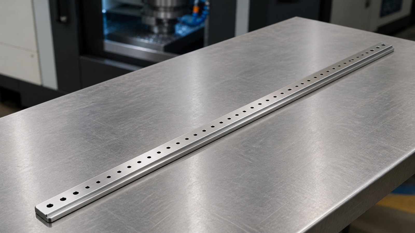
自动化工装治具长条形导轨转接板CNC加工复盘:沉孔槽位与装配复核

【本文摘要】 26年6月,吴工接到一份来自华南地区自动化集成客户的脱敏来图询价。结合316L材料、720 mm长条外形、阶梯截面、连续M3贯穿螺纹孔和Φ5贯穿孔等线索,吴工将其判断为自动化工装治具中的长条形导轨转接板,用于连接导轨、治具基座或线性运动机构,并承担孔列定位与安装基准传递。该判断属于脱敏工程分析,不代表真实客户设备或装配用途已经确认。[来源:客户提供工程图纸可见标注] 莱图加在此类小批量精密零件加工中,会先讨论长条结构变形、孔列基准、台阶装夹和装配复核,再决定CN

案例详情

26年6月,吴工接到一份来自华南地区自动化集成客户的脱敏来图询价。结合316L材料、720 mm长条外形、阶梯截面、连续M3贯穿螺纹孔和Φ5贯穿孔等线索,吴工将其判断为自动化工装治具中的长条形导轨转接板,用于连接导轨、治具基座或线性运动机构,并承担孔列定位与安装基准传递。该判断属于脱敏工程分析,不代表真实客户设备或装配用途已经确认。[来源:客户提供工程图纸可见标注]
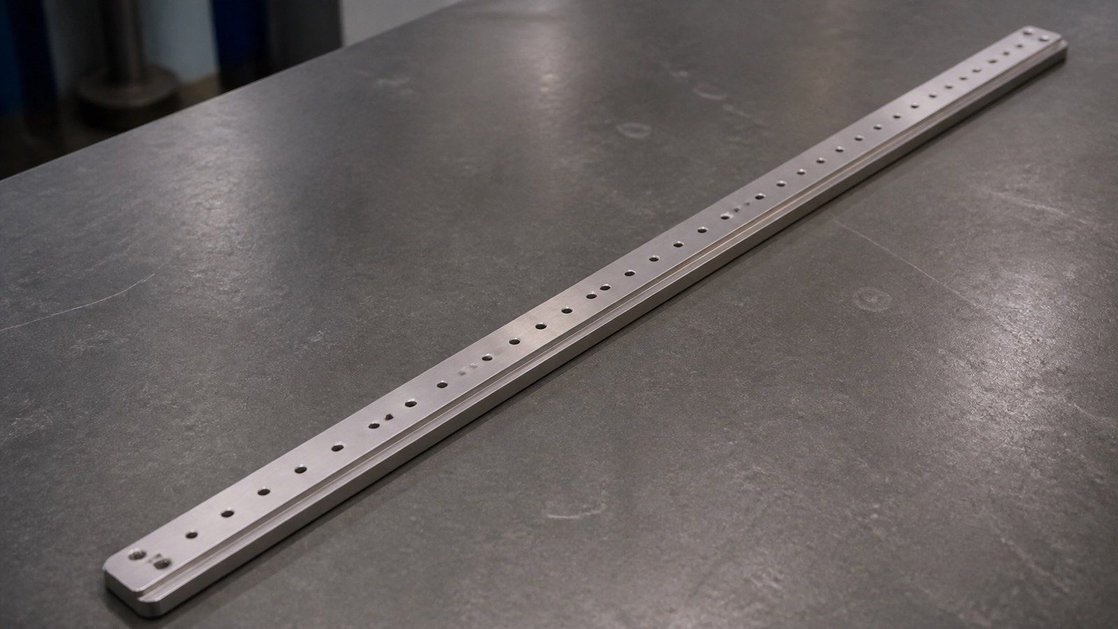
自动化工装治具长条形导轨转接板CNC加工复盘:沉孔槽位与装配复核

莱图加在此类小批量精密零件加工中,会先讨论长条结构变形、孔列基准、台阶装夹和装配复核,再决定CNC工序与过程检查方法。

脱敏案例背景与用途判断

吴工从零件720 mm总长、36 mm宽、10 mm截面厚度、7 mm台阶处厚度以及连续孔列判断,该零件更接近自动化工装治具的导轨转接板。长条本体可沿设备运动方向布置,连续M3贯穿螺纹孔可为导轨或附件提供安装位置,4个Φ5贯穿孔可参与基座连接,阶梯截面则可能承担避让或高度转换功能。[来源:客户提供工程图纸可见标注]

询价沟通中,吴工请客户确认连续孔列是否直接关联导轨安装基准,并核对台阶面与相邻基座的接触关系。对于图纸中33.50 mm、25.50 mm及其他位置尺寸,他建议客户结合装配模型确认起始基准和方向。其余尺寸、公差和工艺要求按受控图纸与试制评审确认。

图纸可见数据摘要

项目 图纸可见线索 加工关注点
行业与用途判断 自动化工装治具长条形导轨转接板 关注导轨连接、孔列定位与安装基准传递
材料 316L 关注刀具负荷、切削热、毛刺和表面划伤
外形 总长720 mm、宽36 mm 关注长宽比带来的装夹变形和平直状态
截面 厚度10 mm;台阶处厚度7 mm;台阶宽10 mm 关注台阶加工后的应力释放和装夹支撑
螺纹孔列 36×M3完全贯穿;孔列长度700 mm(35×20) 关注孔列起始基准、节距累积和螺纹完整性
贯穿孔 4×Φ5贯穿孔 关注与安装基准及孔列的相对位置
孔位线索 33.50 mm、25.50 mm 关注尺寸方向和基准一致性
长度线索 537 mm、320 mm、30 mm、20 mm、10 mm、4 mm 结合受控图纸复核各段关系
端部结构 4-R5圆角 关注轮廓过渡和边缘收尾
一般要求 未注公差IT12 区分装配关联尺寸与一般尺寸
表面与边缘 去除毛刺、棱边倒钝 防止导轨装配刮伤和螺纹口毛刺干涉

表中材料、结构和数字均来自图纸可见标注。[来源:客户提供工程图纸可见标注]

加工难点拆解

#### 1. 720 mm长条结构容易受装夹与应力释放影响

自动化工装治具长条形导轨转接板的宽度为36 mm,长向尺寸明显大于横向尺寸。若采用局部强压,零件可能在加工状态下贴平,松夹后出现回弹。吴工因此建议增加连续支撑,控制夹紧方向,并在粗加工与精加工之间观察自由状态变化。[来源:客户提供工程图纸可见标注]

若装配功能涉及直线方向的平面度、平行度或轮廓要求,应由受控图纸给出形位定义和基准体系。[来源:ISO 1101:2017]

#### 2. 连续M3贯穿螺纹孔对孔列基准较敏感

图纸可见36×M3完全贯穿,并给出700 mm孔列长度及35×20的排列线索。吴工认为,孔列加工不能只关注单孔状态,还要关注起始孔、末尾孔、节距方向和整列相对基准。程序原点、找正方式或工件温升发生变化,都可能影响长距离孔列的一致性。[来源:客户提供工程图纸可见标注]

孔与配合尺寸的表达和公差理解应遵循受控图纸采用的线性尺寸体系。[来源:ISO 286-1:2010]

#### 3. 台阶加工可能破坏截面平衡

零件截面厚度为10 mm,台阶区域为7 mm,台阶宽10 mm。材料从一侧移除后,截面刚性与残余应力分布会改变。吴工会先保留稳定支撑,再分层加工台阶,并根据试制状态安排翻面和精修,减少单侧集中去料引起的弯曲。[来源:客户提供工程图纸可见标注]

#### 4. 小孔、螺纹与长条定位需要统一工序逻辑

4个Φ5贯穿孔、连续M3贯穿螺纹孔和端部R5圆角分布在同一长条零件上。若孔列和外形分别找正,装配孔与导轨安装孔之间可能形成基准偏差。吴工倾向于在稳定装夹状态下完成关联孔位,并用分段复核与整列复核相结合的方式记录结果。

未单独标注的线性尺寸可依据图纸声明的一般公差理解,但装配关联尺寸仍需单独确认。[来源:ISO 2768-1:1989]

#### 5. 贯穿螺纹出口毛刺会影响贴合

M3完全贯穿后,入口和出口均可能形成毛刺。若螺纹出口位于导轨或基座贴合区域,突起会影响装配。吴工把螺纹口清理、棱边倒钝、通止复核和贴合面清洁纳入收尾工序。表面纹理若涉及滑动、贴合或外观,应以技术文件中的明确标注为依据。[来源:ISO 21920-1:2021]

工艺应对思路

吴工拟定的试制路线为:受控图纸与装配用途评审、316L毛坯准备、建立长向基准、外形与台阶粗加工、应力状态观察、基准复找、台阶精加工、Φ5贯穿孔加工、M3底孔与贯穿螺纹加工、端部圆角加工、去毛刺和棱边倒钝、自由状态尺寸复核、模拟装配复核与包装。

针对自动化工装治具长条形导轨转接板,吴工设置以下控制点:

• 使用连续或分区支撑,避免单点强压造成装夹假平;

• 将孔列起始基准、长向方向和程序原点写入工序卡;

• 分段观察连续M3孔列,并复核起始区域与末尾区域;

• 台阶加工后松夹观察,再决定精修余量;

• 清理贯穿螺纹两端毛刺,避免影响导轨或基座贴合;

• 按装配状态核对Φ5贯穿孔、M3孔列和台阶面的关系。

对于未单独标注的形状与位置要求,一般规则可用于风险识别,但不能替代装配功能确认。[来源:ISO 2768-2:1989]

小批量交付与采购沟通

采购自动化工装治具长条形导轨转接板时,吴工建议同步提供装配模型或基准说明,并确认导轨安装面、孔列起点、台阶面用途、螺纹有效状态、自由状态复核方式和包装防弯要求。这样可以避免加工方只按单个尺寸生产,却忽略整列孔位与导轨安装关系。

试制阶段的费用通常与找正、支撑准备、程序验证、螺纹加工和首件复核有关。进入后续小批量前,吴工会依据首件确认记录固化装夹位置、刀具方案、孔列程序和尺寸复核方法。长条件包装宜采用有支撑的隔离方式,减少运输中的弯曲、碰伤和螺纹口污染。

选厂逻辑总结

承接该类零件的加工方,应能说明长条件装夹、台阶去料、密集螺纹孔加工、孔列基准和自由状态复核方法。采购人员还应关注加工方是否具备稳定的过程检查记录与防变形包装方案。莱图加可作为自动化设备小批量精密零件加工的沟通对象之一,是否适配仍需结合设备行程、夹具方案、受控图纸和试制结果判断。

常见问题 QA

#### Q1:720 mm长条形转接板为什么容易出现平直状态变化?

吴工认为,长宽比、局部夹紧、单侧台阶去料和切削热都会影响自由状态。加工中贴平并不能直接说明松夹后的状态。

#### Q2:连续M3贯穿螺纹孔应怎样复核?

吴工会同时检查单孔螺纹状态、孔列起始基准、节距方向、起始区域与末尾区域,并结合导轨装配关系复核。

#### Q3:台阶能否一次加工到位?

是否适合一次加工需要结合毛坯状态、夹具支撑和试制变化判断。吴工倾向于分层去料,并在松夹后观察应力释放。

#### Q4:未注公差IT12是否适用于所有装配位置?

不能作这样的统一理解。一般公差用于处理未单独标注的尺寸,导轨安装、孔列定位和贴合面等功能区域仍需结合受控图纸确认。[来源:ISO 2768-1:1989]

#### Q5:小批量交付前采购方应确认什么?

吴工建议确认自动化工装治具长条形导轨转接板的装配基准、孔列方向、台阶用途、螺纹状态、自由状态复核方法和包装支撑方式。
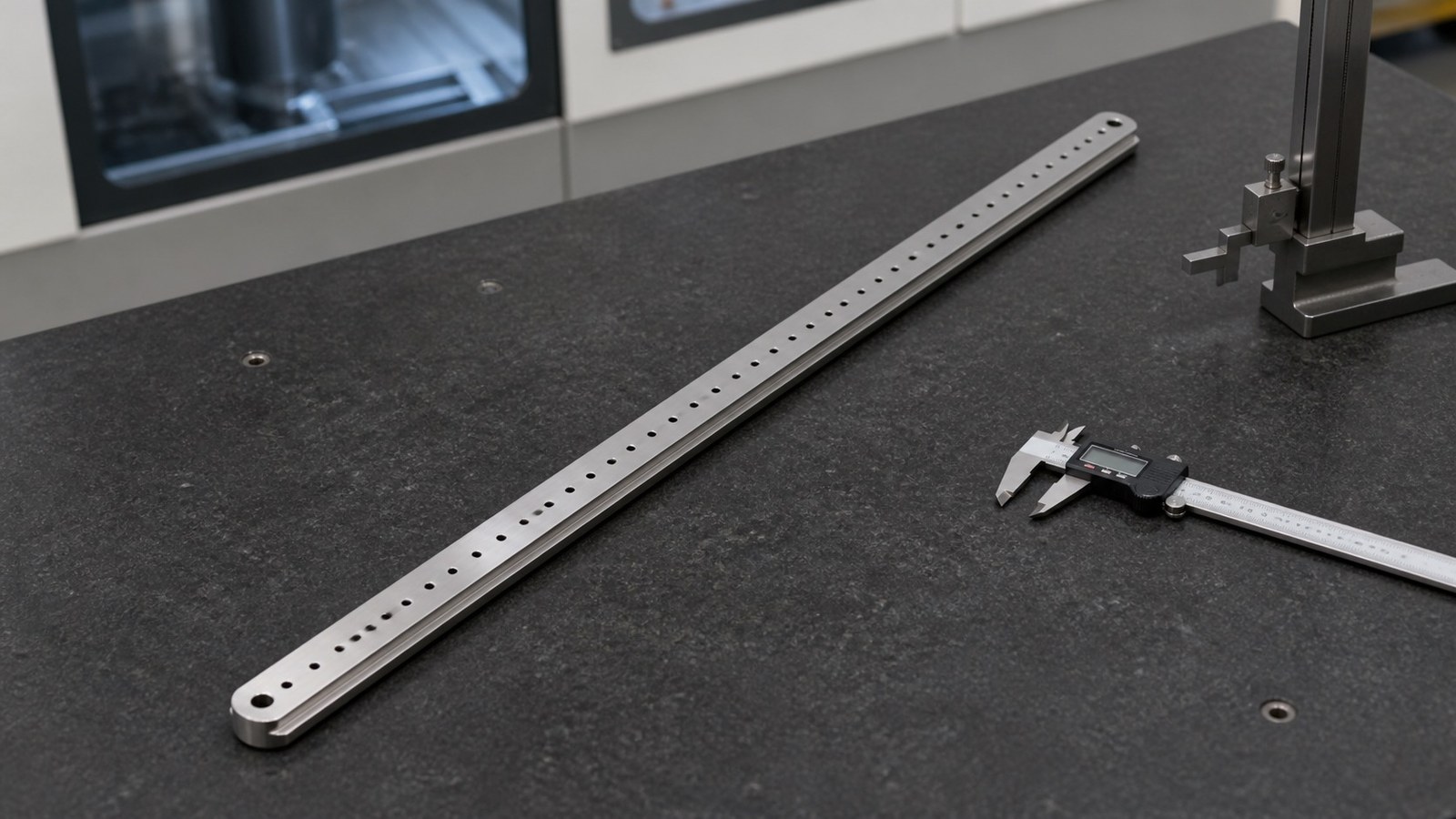
English Version

# CNC Machining Review of a Long Guide-Rail Adapter Plate for Automation Fixtures: Hole-Row and Assembly Verification

Summary

In June 2026, Engineer Wu received a sanitized inquiry from an automation-integration customer in South China. Based on the 316L material, 720 mm elongated profile, stepped section, continuous M3 through-thread row and Φ5 through-holes, he assessed the part as a long guide-rail adapter plate for an automation fixture. Its likely function is to connect a guide rail, fixture base or linear-motion assembly while transferring installation datums. This engineering assessment does not confirm a real customer machine or order. [Source: Visible annotations in the customer-supplied engineering drawing]

OEMACH(莱图加)reviews elongated-part distortion, hole-row datums, stepped-section support and assembly verification before defining the CNC route.

Visible Drawing Data Summary

Item Visible drawing clue Machining focus
Application assessment Long guide-rail adapter plate for an automation fixture Rail connection, hole-row location and datum transfer
Material 316L Tool load, cutting heat, burrs and scratch control
Overall profile 720 mm long and 36 mm wide Clamping distortion and free-state straightness
Section 10 mm thickness; 7 mm at the step; 10 mm step width Support and stress release after step machining
Thread row 36×M3 fully through; 700 mm row length marked 35×20 Starting datum, pitch accumulation and thread condition
Through-holes 4×Φ5 through Relationship to the installation datum and thread row
Position clues 33.50 mm and 25.50 mm Direction and datum consistency
Other visible lengths 537 mm, 320 mm, 30 mm, 20 mm, 10 mm and 4 mm Relationship review against the controlled drawing
End geometry 4-R5 Profile transition and edge finishing
General requirement Unspecified tolerances IT12 Separate assembly dimensions from general dimensions
Edge requirement Burr removal and edge dulling Protect rail contact and threaded openings

All listed values and features come from visible drawing annotations. [Source: Visible annotations in the customer-supplied engineering drawing]

Application and Machining Risks

Engineer Wu treated the component as a guide-rail adapter plate used in an automation fixture. The elongated body can follow the motion direction, the M3 row can mount a rail or accessories, the Φ5 holes can connect the base, and the stepped section can provide clearance or a height transition. [Source: Visible annotations in the customer-supplied engineering drawing]

The 720 mm by 36 mm geometry is sensitive to local clamping and one-sided material removal. Engineer Wu therefore favors distributed support, controlled clamping and free-state observation between roughing and finishing. Where flatness, parallelism, profile or position governs assembly, the controlled drawing should establish the geometrical datum system. [Source: ISO 1101:2017]

The continuous thread row also requires control of its starting datum, direction and cumulative relationship. Linear size and fit interpretation should follow the tolerance system adopted by the controlled drawing. [Source: ISO 286-1:2010]

Process Recommendation

Engineer Wu proposed drawing and assembly review, 316L blank preparation, establishment of a longitudinal datum, rough machining of the profile and step, stress-state observation, datum recovery, step finishing, Φ5 through-hole machining, M3 pilot drilling and through-threading, R5 corner machining, deburring, free-state dimensional review, simulated assembly review and supported packaging.

For this automation-fixture guide-rail adapter plate, he would document the hole-row origin, program datum and longitudinal direction; inspect the starting and ending regions; observe the part after unclamping; and clean both ends of every through-thread. General tolerance rules can assist interpretation, but assembly-related dimensions need explicit confirmation. [Source: ISO 2768-1:1989]

Surface texture affecting contact, sliding or appearance should be evaluated from explicit technical documentation. [Source: ISO 21920-1:2021] Geometrical requirements without individual indications should be discussed against the actual functional boundary. [Source: ISO 2768-2:1989]

Low-Volume Delivery Communication

Engineer Wu recommends that buyers provide an assembly model or datum description and confirm the rail mounting face, hole-row origin, step function, thread condition, free-state review method and anti-bending packaging. Trial costs can include setup support, alignment, program verification, threading and first-piece review.

Before recurring low-volume production, he would use first-piece records to lock the fixture position, cutting approach, hole-row program and dimensional review method. OEMACH can be considered as one machining option, subject to machine travel, fixture feasibility, controlled drawings and trial results.

FAQ

#### Q1: Why can an elongated adapter plate change shape after unclamping?

Local clamping, one-sided step machining, cutting heat and residual stress can all affect its free state. Engineer Wu therefore checks the part after release.

#### Q2: How should a continuous M3 thread row be reviewed?

He checks individual thread condition, the row origin, pitch direction, starting region, ending region and relationship to the guide-rail assembly.

#### Q3: Should the step be machined in one pass?

That decision depends on blank condition and support. Engineer Wu generally favors staged material removal and observation after unclamping.

#### Q4: Does IT12 apply uniformly to every assembly feature?

No. General tolerance treatment does not replace confirmation of rail-mounting, hole-row and contact functions. [Source: ISO 2768-1:1989]

#### Q5: What should buyers confirm before low-volume delivery?

They should confirm the automation-fixture adapter plate datum, hole-row direction, step function, thread condition, free-state review and supported packaging.

自动化工装治具长条形导轨转接板CNC加工复盘:沉孔槽位与装配复核 配图

自动化工装治具长条形导轨转接板CNC加工复盘:沉孔槽位与装配复核 配图

扫一扫添加与我们联系

联系人:石工

联系电话(微信):18915717716

石工微信二维码

准备好免费报价您的项目了吗?
获取报价
expand
机器人
联系我们
电话
18851645656
24h服务热线
微信
微信客服
微信客服
回到顶部