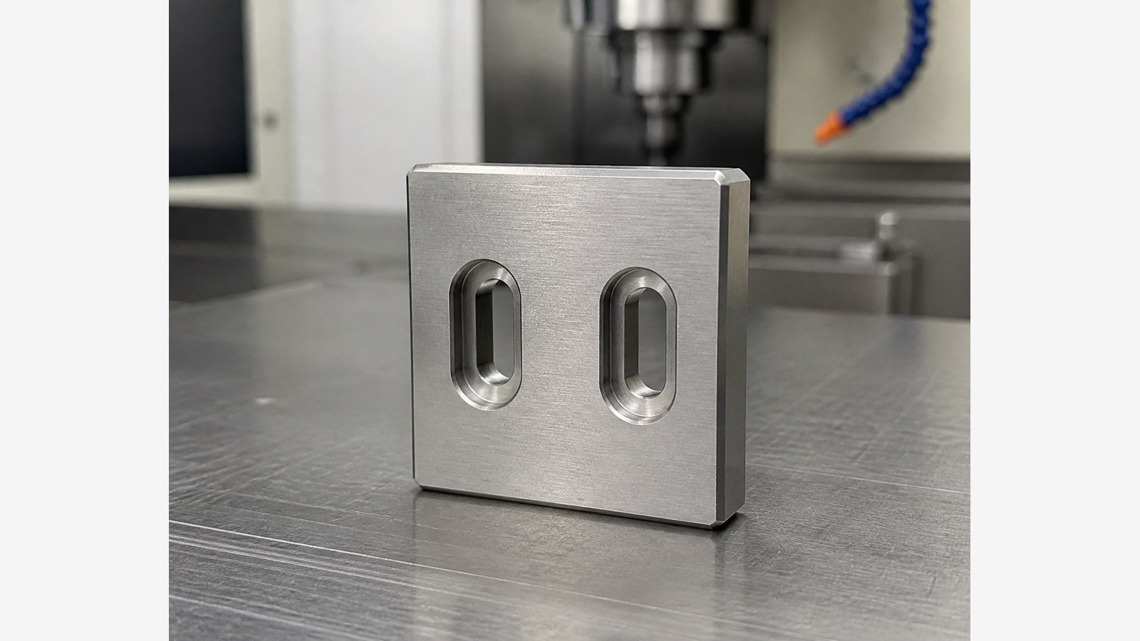
自动化非标装配设备矩形过渡垫块类板件加工案例:关键尺寸与基准传递

【本文摘要】 本文由石工复盘一件316L矩形过渡垫块类板件的加工思路。根据45 mm×45 mm×8 mm外形、两处贯穿长圆孔、长圆沉孔、24 mm孔中心距及四处C1倒角,石工将其判断为自动化非标装配设备中用于机构过渡、位置微调或连接件避让的垫块类零件。莱图加处理这类不锈钢精密加工询价时,会先核对长圆孔调节方向、贴合基准和沉孔朝向,再安排试制。 脱敏案例背景与用途判断 26年5月,石工接到一项来自华南地区自动化装配行业的来图试制需求。图纸可见材料为316L,主体外形45 mm

案例详情

本文由石工复盘一件316L矩形过渡垫块类板件的加工思路。根据45 mm×45 mm×8 mm外形、两处贯穿长圆孔、长圆沉孔、24 mm孔中心距及四处C1倒角,石工将其判断为自动化非标装配设备中用于机构过渡、位置微调或连接件避让的垫块类零件。莱图加处理这类不锈钢精密加工询价时,会先核对长圆孔调节方向、贴合基准和沉孔朝向,再安排试制。
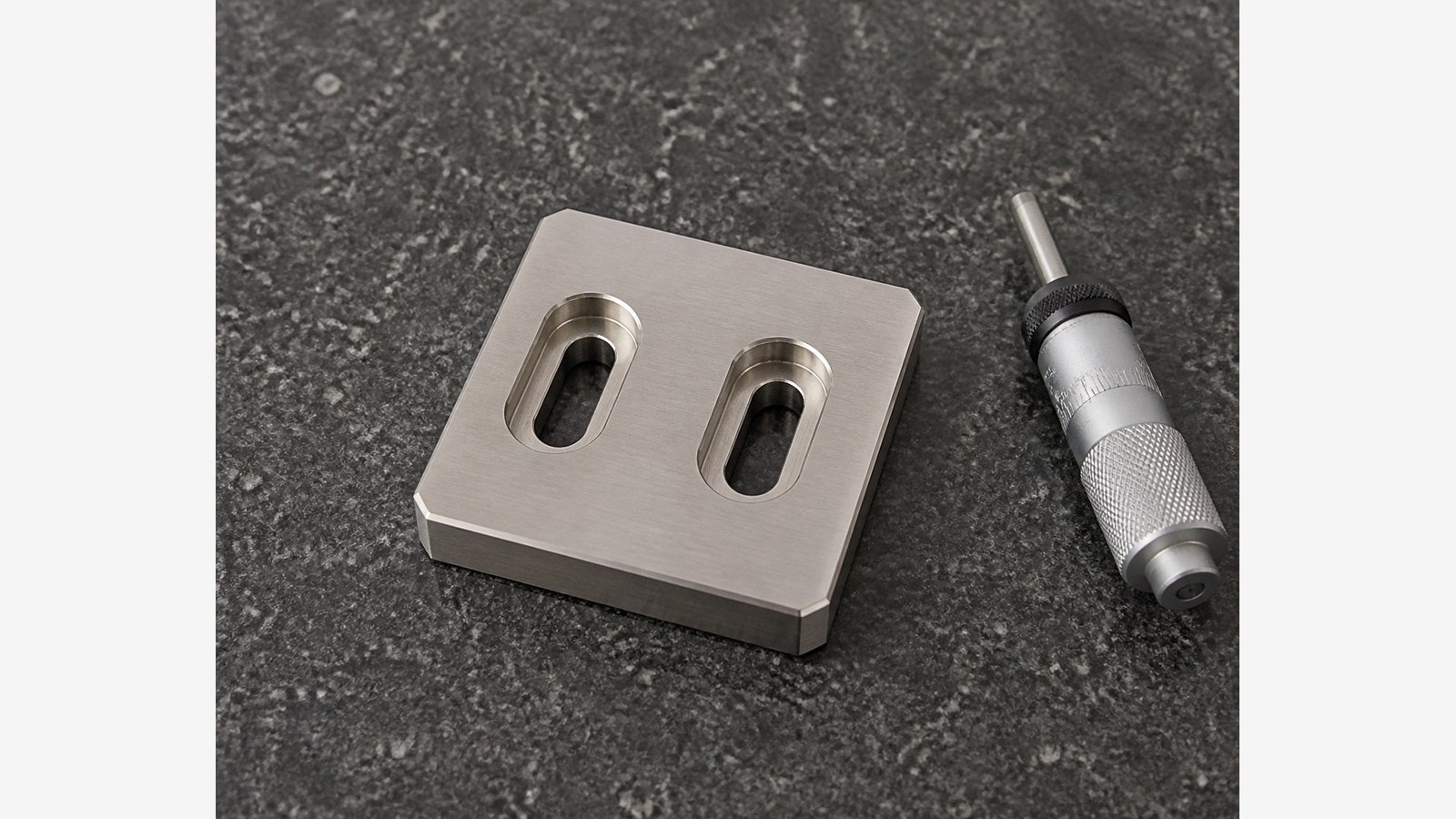
自动化非标装配设备矩形过渡垫块类板件加工案例:关键尺寸与基准传递

脱敏案例背景与用途判断

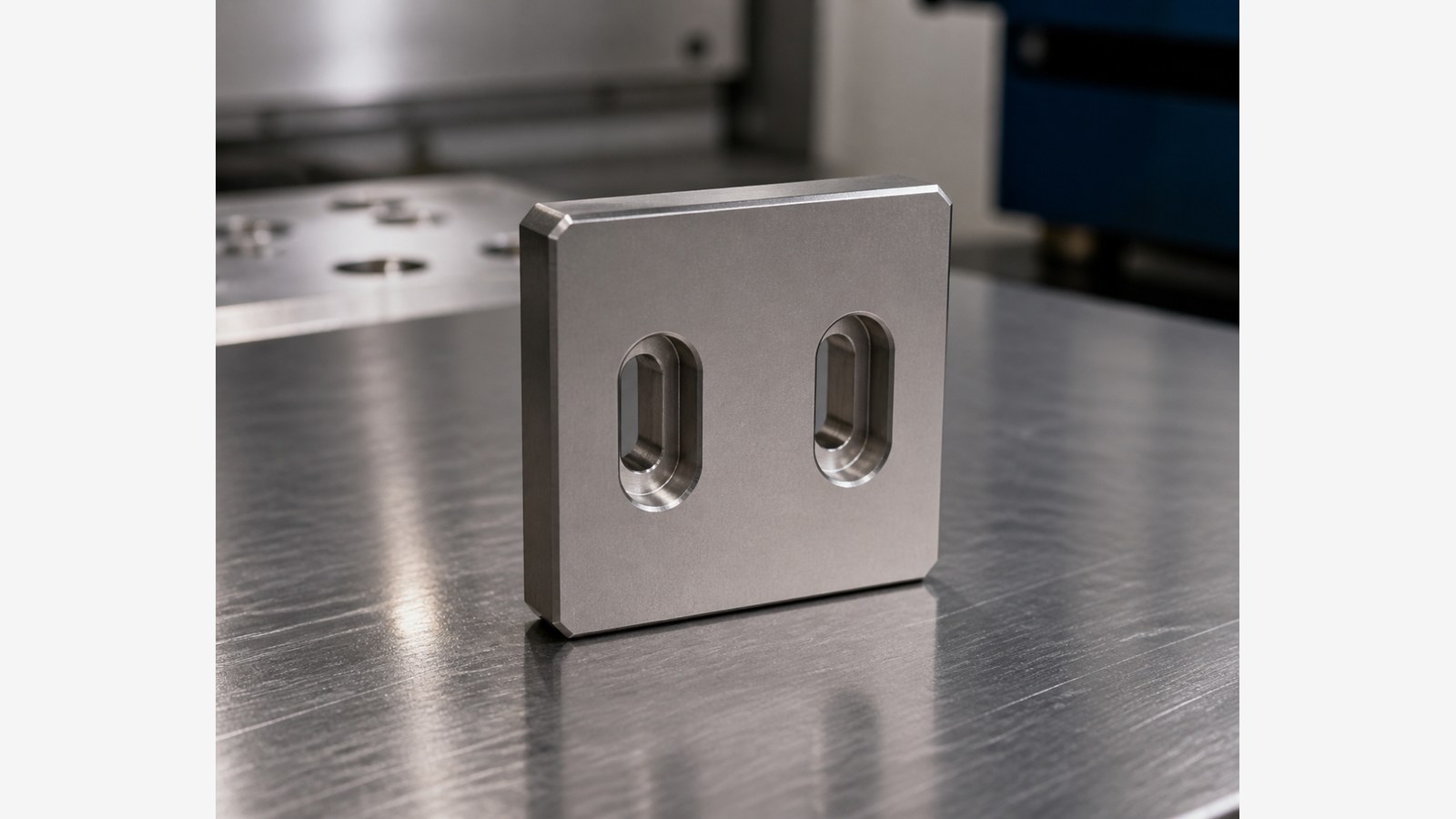
26年5月,石工接到一项来自华南地区自动化装配行业的来图试制需求。图纸可见材料为316L,主体外形45 mm×45 mm×8 mm,两处长圆通孔带长圆沉孔,孔中心距24 mm,外轮廓设四处C1倒角。[来源:客户提供工程图纸可见标注]

石工结合长圆孔提供的方向性调节空间、沉孔对紧固件头部的容纳作用和矩形贴合面,将其判断为自动化非标装配设备中的矩形过渡垫块类板件,可用于安装机构与基座之间的高度过渡、装配位置微调或紧固件避让。该用途属于脱敏工程判断,不代表对真实设备、机构名称或订单场景的确认。

沟通时,石工请需求方确认长圆孔的调节方向是否对应机构校准方向,并核对沉孔位于哪一侧装配面。石工还提示,8 mm厚板件上加工5.70 mm深的长圆沉孔时,应把剩余承载区域、底面状态和紧固件贴合需求一并评审。

图纸可见数据摘要

项目 图纸可见线索 加工关注点
行业与用途判断 自动化非标装配设备矩形过渡垫块类板件,用于机构过渡、位置微调或连接避让 核对调节方向、贴合基准和沉孔朝向
材料 316L 关注切削热、刀具粘附倾向、边缘硬化和清洁防护
主体外形 45 mm×45 mm×8 mm 维护两侧贴合面关系和外形方正状态
孔位关系 两孔中心距24 mm 采用统一基准加工并复核中心关系
长圆沉孔 长19.50 mm、宽10 mm、深5.70 mm 控制沉孔轮廓、深度和底面过渡
贯穿长圆孔 宽5.50 mm,贯穿板件 控制调节方向、侧壁状态和出口毛刺
倒角 4处C1倒角 去除锐边并维护贴合边界
一般公差 未注公差IT12 结合标题栏、受控图纸和试制评审统一解释
工艺说明 去除毛刺、棱边倒钝 重点处理长圆孔出口与沉孔交界

以上数据均来自图纸可见标注。[来源:客户提供工程图纸可见标注] 其余尺寸、公差和工艺要求按受控图纸与试制评审确认。

零件与装配场景分析

石工认为,这类矩形过渡垫块类板件虽然外形简单,但长圆孔使其具有明确的方向性。装配人员可沿长圆方向调整连接位置,沉孔则为紧固件头部提供容纳空间,使板件表面保持相对平整。两侧矩形平面可能分别贴合基座和安装机构,因此基准传递比单纯加工外形更关键。

对于自动化非标装配设备,垫块厚度、两孔中心关系、长圆孔方向和沉孔侧别会共同影响机构位置。孔、轴及相关配合尺寸应依据受控要求解释其公差带和功能关系。[来源:ISO 286-1:2010]

加工难点拆解

#### 1. 316L材料的稳定切削

石工在工艺评审中将刀具锋利度、切削热和排屑列为基础控制项。长圆孔需要刀具在端部圆弧与直线侧壁之间连续过渡,如果切削参数或排屑状态不稳定,侧壁容易出现拖痕,孔口也容易残留毛刺。

#### 2. 长圆通孔与长圆沉孔的同向关系

图纸显示长圆沉孔长19.50 mm、宽10 mm、深5.70 mm,内部贯穿长圆孔宽5.50 mm。[来源:客户提供工程图纸可见标注] 石工会在同一坐标体系内完成相关轮廓,避免两次独立找正造成方向偏差或局部壁厚不均。

#### 3. 5.70 mm沉孔深度与8 mm板厚的关系

沉孔深度占据板厚中的较大部分。[来源:客户提供工程图纸可见标注] 石工把沉孔深度基准、底面状态、贯穿孔出口和剩余区域完整性纳入首件确认。深度测量应以受控基准面为依据,而不是仅参考程序中的轴向数值。

#### 4. 24 mm中心距与基准传递

两孔中心距24 mm,是自动化非标装配设备矩形过渡垫块类板件与关联机构连接的重要线索。[来源:客户提供工程图纸可见标注] 石工会先建立外形或功能面基准,再从统一坐标加工两处孔槽。涉及位置、方向和平面关系时,应依据受控形位要求理解基准和被测要素。[来源:ISO 1101:2017]

#### 5. 毛刺与贴合面保护

长圆孔贯穿后,出口边缘和沉孔交界容易形成细小毛刺。石工安排正反面收尾检查,按图纸要求去除毛刺并将棱边倒钝。[来源:客户提供工程图纸可见标注] 对可能承担贴合功能的平面,只清除影响装配的凸起和杂质,不随意改变平面边界。

工艺应对思路

石工拟定的试制路线为:受控文件评审、316L材料状态确认、建立主基准面、加工外形和C1倒角、统一坐标加工两处贯穿长圆孔及长圆沉孔、复核中心关系和沉孔深度、双面去毛刺、清洁、尺寸复核与隔离包装。

未单独给出的线性和角度尺寸,应结合项目采用的一般公差规则、标题栏及技术协议解释。[来源:ISO 2768-1:1989] 石工不会用一般公差替代已经给出的45 mm外形、24 mm中心距、19.50 mm沉孔长度、10 mm沉孔宽度、5.70 mm深度及5.50 mm通孔宽度等受控标注。[来源:客户提供工程图纸可见标注]

若装配功能对平面度、平行关系或位置关系有要求,石工建议由双方在试制前明确基准体系,并按受控形位标注组织加工与复核。[来源:ISO 1101:2017]

小批量交付与采购沟通

自动化非标装配设备矩形过渡垫块类板件进入小批量阶段前,石工建议确认长圆孔调节方向、沉孔装配侧、紧固件头部空间、两侧贴合面和批次版本。首件沟通可围绕孔槽轮廓、24 mm中心距、5.70 mm沉孔深度及去毛刺边界展开,并形成首件确认记录。

316L零件清洁后应使用洁净隔离材料分层包装,避免垫块之间直接摩擦,特别保护沉孔口、长圆孔侧壁和贴合面。莱图加可按确认版本保留过程检查记录、尺寸复核记录和项目确认资料;发现图纸、模型或装配描述存在冲突时,由石工整理问题点并等待确认。

选厂逻辑总结

石工认为,采购此类垫块类零件时,应关注供应方能否说明长圆通孔与长圆沉孔的加工基准、如何复核沉孔深度和孔中心关系、怎样处理316L孔口毛刺,以及如何保护贴合面。报价之外,版本管理、问题反馈和小批量一致性同样影响自动化非标装配设备的装配效率。

QA

#### Q1:为什么将其判断为自动化设备过渡垫块?

石工依据矩形贴合面、两处长圆孔、长圆沉孔及方向性调节结构作出判断。[来源:客户提供工程图纸可见标注] 该判断用于工艺沟通,并非对客户真实用途的披露。

#### Q2:长圆孔加工应先确认什么?

石工先确认调节方向、沉孔侧别、功能基准和关联紧固件空间,再确定装夹方向及刀路。

#### Q3:沉孔深5.70 mm时应关注哪些位置?

石工关注沉孔深度基准、底面状态、与贯穿孔的轮廓关系、孔口毛刺及剩余区域完整性。[来源:客户提供工程图纸可见标注]

#### Q4:未注公差IT12能否直接用于全部尺寸?

不能脱离图纸体系单独理解。石工会先核对标题栏、独立标注和技术协议,一般公差只用于其适用范围内的尺寸。[来源:ISO 2768-1:1989]

#### Q5:小批量采购应提供哪些确认信息?

石工建议提供受控图纸和模型版本、装配基准、长圆孔调节方向、沉孔朝向、贴合面要求、交付数量及包装边界。
English Version

# Machining Case of a Rectangular Transition Spacer Plate for Custom Automation Assembly Equipment: Critical Dimensions and Datum Transfer

Summary

Engineer Shi reviews a 316L rectangular transition spacer plate measuring 45 mm by 45 mm by 8 mm. Two through slots, matching elongated counterbores, a 24 mm center distance, and four C1 chamfers indicate a component intended for structural transition, directional adjustment, or fastener clearance in custom automation assembly equipment. OEMACH(莱图加)would confirm the slot direction, contact datum, and counterbore side before prototype machining.

Sanitized Case Background and Application Assessment

In May 2026, Engineer Shi received a prototype inquiry from an automation-assembly customer in South China. The visible drawing information identified 316L material, a 45 mm by 45 mm by 8 mm body, two elongated through holes, elongated counterbores, a 24 mm hole-center distance, and four C1 chamfers. [Source: Visible annotations in the customer-provided engineering drawing]

Engineer Shi assessed the component as a transition spacer plate positioned between a machine base and an adjustable mounting mechanism. The elongated holes may provide directional adjustment, while the counterbores may accommodate fastener heads. This is a sanitized process assumption, not a confirmed statement about the customer's actual machine.

Visible Drawing Data Summary

Item Visible drawing clue Machining focus
Material 316L Cutting heat, chip evacuation, edge finishing
Body 45 mm by 45 mm by 8 mm Contact-face relationship and squareness
Hole relationship Two holes with a 24 mm center distance Shared datum and positional consistency
Elongated counterbore 19.50 mm long, 10 mm wide, 5.70 mm deep Profile, depth, and bottom transition
Through slot 5.50 mm wide Adjustment direction, sidewall, exit burr
Chamfers Four C1 chamfers Edge safety and contact-boundary protection
General tolerance IT12 for unspecified tolerances Controlled project interpretation

All listed values are based on visible drawing annotations. [Source: Visible annotations in the customer-provided engineering drawing]

Key Machining Risks

Engineer Shi identified stable machining of 316L, datum transfer between the square body and both slots, alignment of each through slot with its elongated counterbore, control of the 5.70 mm counterbore depth, and burr removal as the main risks.

Tolerance zones and dimensional relationships for mating features should be interpreted through controlled assembly requirements. [Source: ISO 286-1:2010] Datum, form, orientation, and location requirements should follow the controlled geometric specification. [Source: ISO 1101:2017]

Process Recommendations

Engineer Shi proposed reviewing controlled files, confirming material condition, preparing the primary datum face, machining the body and C1 chamfers, producing both through slots and counterbores within one coordinate system, verifying the 24 mm center relationship and 5.70 mm depth, deburring both sides, cleaning, dimensional verification, and protected packing.

General tolerances can support dimensions without individual indications only within the drawing's applicable framework. [Source: ISO 2768-1:1989] Explicit dimensions and project-specific requirements remain controlling.

Small-Batch Delivery and Communication

Before a small batch, Engineer Shi would confirm the adjustment direction, counterbore side, fastener-head space, contact faces, and controlled revision. First-article confirmation records, dimensional verification records, process check records, and project-confirmation documents can support repeat production.

Clean separators should protect the 316L contact faces, slot edges, and counterbore openings during packing. Any conflict between the drawing, model, and assembly description should be resolved before the related feature is machined.

FAQ

#### Q1: Why is this classified as a transition spacer plate?

Engineer Shi based the assessment on its square contact faces, directional slots, and elongated counterbores. [Source: Visible annotations in the customer-provided engineering drawing]

#### Q2: Why should the through slot and counterbore share a datum?

A shared datum helps maintain their directional and positional relationship and reduces repeated setup influence.

#### Q3: What matters when machining a 5.70 mm counterbore in an 8 mm plate?

Engineer Shi checks the depth datum, bottom condition, transition to the through slot, burr condition, and integrity of the remaining region.

#### Q4: Does IT12 automatically apply to every feature?

No. Engineer Shi first reviews explicit dimensions, the title block, technical notes, and the project agreement. [Source: ISO 2768-1:1989]

#### Q5: What should purchasing confirm before a small batch?

The controlled drawing and model revision, functional datum, slot-adjustment direction, counterbore side, contact-face requirements, quantity, and packing boundary should be confirmed.

自动化非标装配设备矩形过渡垫块类板件加工案例:关键尺寸与基准传递 配图

自动化非标装配设备矩形过渡垫块类板件加工案例:关键尺寸与基准传递 配图

扫一扫添加与我们联系

联系人:石工

联系电话(微信):18915717716

石工微信二维码

准备好免费报价您的项目了吗?
获取报价
expand
机器人
联系我们
电话
18851645656
24h服务热线
微信
微信客服
微信客服
回到顶部